Showing posts with label Schematics. Show all posts

Saturday, August 1, 2026

Adding waveforms to the Gakken (Simple Saw Animator)

     As part of our ongoing series on the Gakken SX-150 mk II, I've been thinking about various ways it can be enhanced. One obvious shortcoming is the complete lack of waveform options. We have a saw; that's it. There's no second oscillator, nor sub oscillator.

Hip to Be Square

    A simple addition is a square waveform. All we need to do is compare the saw to a midpoint voltage. If the saw is above the midpoint, the output is high, else it's low. This raises the question: what is the midpoint? We can find this empirically, by measuring the waveform with an oscilloscope, but there's no guarantee a different Gakken will have the same midpoint. The midpoint might also drift with time, or old batteries. It's best not to build the circuit around an unknown like that, so let's remove it by adding a highpass filter and rebiasing the saw.

Saw to Square conversion

    There it is, rebiased around 2.5V. If we'd like to change the width of the pulse, we can vary the voltage at the inverting input of the opamp.

Pulse width modulation

    So, we get Pulse Width Modulation (PWM) for free, just by providing a voltage. We do have to be careful to match the range of the CV to the amplitude of the saw, or the PWM range won't be what's expected.

You're Thinking of Someone With Two Knives

    Wouldn't it be nice if we had a second oscillator to thicken up the sound? Well, maybe we can fake a second saw wave. Back in 1978, Bernie Hutchins published a "waveform animator" that does just that. 

    It works by comparing a saw (or triangle) waveform to a fixed voltage, then summing the saw and the output of the comparator. The comparator output shifts a chunk of the saw up, and the rest of it down, in a way that effectively changes the phase of the saw. It's as if it moved forward/backward in time relative to the original, just like a second saw would do if it were a slightly different pitch.

Fig 2 from Electro Notes #87

    It's a really great trick, and it only has the small catch that the resulting waveform now has a DC offset, due to the comparator output being lopsided. This is accounted for by mixing in some of the CV that drives the comparator.

From All Angles

    Now that we know it's possible to fake a second saw, we can riff on the idea, and maybe make something that's more in the minimalist spirit of the Gakken.

    The original design mixed an equal proportion of the comparator's PWM output with the saw to get the phase shifted saw. We don't have a use for it by itself, and we really just want the mix of the two saws. Turns out we can get the same result by just dropping the amplitude of the PWM signal. It yields the same proportion of phase-shifted saw to original saw.

    Here's a comparison between two actual saws and our half-amplitude-PWM circuit:

Two saws vs one saw + PWM

    Neat, huh? The PWM signal (red) slides a segment of the saw upwards to represent our phantom, second saw. This has saddled us with the DC offset problem discussed earlier, but we have an otherwise perfect emulation of two saws. 

    We can see the waveform starts with a full amplitude saw that breaks into two uneven peaks. Those peaks then level out into a saw that's twice the frequency but half the amplitude, then the process reverses.

Two Are Better Than One

    The original wave animator circuit was meant to be duplicated multiple times to get additional shifted copies of the wave. There would be a new LFO, inverting amp, comparator, and summing amp per copy. That's a bit excessive for our little Gakken, but we can take inspiration from the idea.

    Mixing in one PWM signal gave us a second saw, so maybe we can tack on another PWM signal to get another saw. If we invert the phase of our existing PWM to make this "new" PWM signal, it'll simply cancel out in the mix, returning us to a single saw.

    If we invert the saw instead, we get a different PWM signal, one with pulses that "grow" in the opposite direction and offset a different portion of the saw. If we make sure it has the same pulse width, but opposite polarity of the first PWM signal, it will even cancel out the DC offset that we introduced.

PWM #2 generated from an inverted saw

    We can see from the "PWM Mix" signal that the combination of the two signals is balanced around a midpoint with an even amount of time spent above and below.

    If we mix in a specific amount of the inverted saw, we can see the multi-saw waveform emerge, this time with an additional peak.

The full saw animator

    There we have our full saw animator built around just 3 op-amps. The fourth is left as an optional buffer.

There's What's Right and There's What's Right

    Clearly it's easy to add square waves, so let's come up with another one. Adding a square sub oscillator is an obvious DIY move. All we need is some sort of counter and a reasonable pulse to feed it, then out comes a square wave an octave down. The counter is performing a divide by two operation on the number of incoming pulses. One pulse out for every two in. This amounts to a divide by two operation being performed on the frequency of the incoming pulses also.

Adding a d-type latch to generate a sub octave

    We tap off of one of our PWM signals so that we can get a clean pulse for our counter. Using an inverter keeps the sub aligned with the falling edge of the saw, rather than the other edge of the PWM pulse. This is because the counter only counts on the rising edge of the clock.

Never the Twain Shall Meet

    Much like the saw, things get interesting when we mix our waveforms together in specific ratios. Here's the sub mixed with both PWM signals.

Pulse and sub mix

    Look at that. We get a new waveform, a stepped saw that's an octave down. This is similar to the Korg Poly-800's saw that it builds from different octaves of square waves.

Submerge

    Now that we have our square sub oscillator, we can combine it with our saw to get a triangle sub oscillator. All we have to do is invert the saw when the sub is low, giving us two back-to-back right triangles that form an isosceles triangle.

    We already have an inverting amplifier that gives us an inverted saw. We could use an analog switch to toggle between the inverted and non-inverted saws, but the non-inverted one isn't buffered and would get rebiased as we connect and disconnect it.

    We can instead borrow a trick used in attenuverters. Rich Holmes has a nice breakdown of how they work here, and we'll borrow one of his images:

Simple attenuverter - richardsholmes.com

    We can imagine the pot with the wiper at the bottom (counterclockwise) extreme. The non-inverting input (pin 3) of the opamp is shorted to ground, and we get an inverted output. At the other extreme, pin 3 instead sees the full input voltage, and we got a non-inverted output.

    We can use a SPDT switch to do the same thing: connect the non-inverting input to ground or the saw wave, alternately. This input pin pulls virtually no current, so it doesn't upset the bias of the saw.

sub triangle wave

    There is a small hiccup where the saw is inverted, but this is typically inaudible due to how narrow it is.

    Now we have a saw, two pulse waves, a square sub, and a triangle sub. Depending on how we mix them, we can also get two flavors of animated "super" saw (one PWM or two), a stepped sub saw, and a regular sub saw. It's worth pointing out that the triangle sub conflicts with the animated saw, since it robs us of the inverted saw half the time. The combination does still produce an interesting, half-animated triangle though.

Saturday, April 25, 2026

Gakken LFO Modifications (and Faking Log Pots with Code)

    We're continuing to look at the Gakken SX-150 mk II and investigate how we can improve it. Today we're focusing on the LFO. It's a classic design: integrator and schmitt trigger. It even has a crude reset feature.

Gakken SX-150 mk II stock LFO

MIDI

    As with everything else, we'd like to add MIDI control. We can substitute a digipot in place of the rate potentiometer and call it a day, right? Well, yes, but the original pot isn't doing its job particularly well. The lower end of the frequency range has a jump in it that makes it quite touchy, as does the top, and most of the rest of the range yields overly-fast results.

It's Log?

    What went wrong? The designers avoided using log pots, and this is a situation that calls for a log pot. They instead approximated a log taper by putting R66 in parallel with half of the linear pot. Out of curiosity, we can break the circuit down and figure out what the actual taper is.

    We can think of the pot as two resistances that are joined by the wiper, forming a voltage divider. The ratio of resistances determines what proportion of the input voltage we'll get at the output. If we let `t` represent the top resistance, and `b` represent the bottom, this formula gives the ratio between input and output:

`b/(t+b)`

    Since these two resistances are just portions of the same pot, they'll always sum to the full resistance of the pot. If we use `x` to represent the position of the pot from 0-1, and `r_1` for the total resistance, we can define `t` and `b` like so:

`t=r_1(1-x)`
`b=r_1x`

    Now we just need to include the resistor that's in parallel with `b`. The parallel resistor formula is:

`(r_1r_2)/(r_1+r_2)`

    We can plug in `b` and our fixed resistor of 2.2(k) to get the actual value for the bottom half of the divider, that we'll call `B`:

    `B=(2.2b)/(2.2+b)`

    This takes the place of `b` in our first formula, and `r_1 = 50`, giving us this stack of formulas that we can put into Desmos:

`t=50(1-x)`

`b=50x`

`B=(2.2b)/(2.2+b)`

`y=B/(t+B)`

Gakken fake log taper

    We can see there's a funny lip at the low extreme that explains it being touchy. The high side shoots up rather steeply also. While it's better than a linear response, it's not a good enough log approximation for this LFO. If we naively put a digipot in its place, we'll have the exact same issues.

Better than Bad

    Since MIDI CCs only have 128 steps, and our digipots have 256, there's a little wiggle room in how we progress through the positions. We can map the 128 steps onto positions that help compensate for the inaccuracies of the log approximation.

    We'll define a curve to do this compensation, but it has to be one that can be realized with the limited positions of the digipot. It we pick a curve that's too shallow, one step of the CC change won't push us up to the next position of the digipot, and we'll have wasted one of our precious 128 steps.

digipot trying to resolve shallow curves

    Above we can see a line in green that yields 2 digipot steps per 1 CC step, and an orange line that yields 1 digipot step per 1 CC step. Finally we have the red line that requires less than one digipot step per CC, showing the plateaus where a change in CC had no impact.

What Rolls Down Stairs?

    Now let's think about what curve would help fix up our taper. We need to reduce the lip at the bottom, and smooth the spike at the top by progressing through those more slowly. The middle is a little unresponsive, so we can speed through that to balance things out. This slow-on-the-ends curve is called an s-curve.

    One of the simpler s-curve functions is the logistic function that takes this form:

`L/(1+e^(-k(x-x_0))`

    `L` scales the function vertically, while `k` sets the severity of the curves, and `x_0` defines the midpoint. As in previous posts, we want to normalize the curve to a range of 0-1, so we can make `L = 1`. We want the curve roughly centered in our range, so we'll let `x_0 = .5`. `k` we'll have to play with so we don't end up with too shallow of a curve.

    Just like last time we can make the function pass through (0,0) by subtracting the y intercept. We can also force it to pass through (1,1) by dividing by the value of `y` when `x = 1`. By doing both we have a normalized function that lets us experiment with values of `k`.

    Here's a first guess of `k=10`. I've added short line segments that show our minimum angle of x/2.

logistic curve where `k=10`

    This is too shallow to resolve on the digipot without wasting CC steps. By adjusting `k` until the ends hugged the bounds we've set, I settled on a value of 5.2.

logistic curve where `k=5.2`

    By taking the result of this function, and plugging it in for x in our old log-approximation formula (blue), we can see our new potentiometer taper in orange, compared to a more idealized curve in black

compensated taper vs original approximation vs "ideal"

    The black line is a target curve I came up with arbitrarily. I used the form `n^x`, normalized it, and picked a value of `n` that passes through the original curve at `x=.5`. You can see the compensation got us maybe halfway to the target. It's not great, but it's a free gain in accuracy given we're just being smarter about how we use our potentiometer.

Everyone Wants a Log

    How does this work in practice? It's a noticeable improvement, but it's not ideal. The ends are still jumpy, and the middle isn't terribly responsive. We can improve the resolution of the digipot by combining two digipots as if they were one. If we put them in series we get twice the steps, plus we gain the ability to adjust the top and bottom separately, giving us many more ratios of resistance. Still, we're chasing this log taper using low-resolution linear means, and that's something of a losing proposition.

It's Big, it's Heavy, it's Wood

    The real solution is to treat the LFO like the VCO, and give it the exponential current source that it deserves. There's one big difference though: the VCO is a saw core, and the LFO is a triangle core. This means we have to not just sink current from it, but source current to it. How do we make our current source bidirectional? 

    Wikipedia defines the Operational Transconductance Amplifier like this:

...an amplifier that outputs a current proportional to its input voltage. Thus, it is a voltage controlled current source.

    Crucially, when the input voltage goes negative, so does the output current. That's just what we need. There's a second current input (pin 1) that defines the magnitude of the the output by multiplying it with the voltage input. We can hook up our single-direction exponential current source here, while using the voltage input to change the direction of the output, thus controlling the triangle. 

Exponential voltage control for the LFO

It's Good

    This gives a much better response than misused linear pots. Notice we had to change the timing cap, C24. It was simply too large, and required the OTA to push excessive current for higher LFO rates. We can now achieve both much higher, and lower frequencies than before, despite the 10x smaller cap. The CV input just needs to be hooked up to a microcontroller's DAC, or anything else that can produce a usable voltage.

Fits on Your Back

    We spent so long investigating the math of the approximate log taper that it'd be a shame to do nothing with it. There is another spot in the circuit where they appear to use the same trick, and it also relates to the LFO. It's the LFO Depth adjustment.


LFO depth log approximation

    We can tell from the ratio of the pot value to the resistor that this is a much more gentle curve than the LFO rate pot. That means we have a better shot at being able to compensate for it. We can plug the new values into our existing curve and see the taper in blue. By playing with the values of the s-curve we can match the compensated curve (orange) to our target curve in black.

LFO Depth curve. Before: blue, after: orange 

    The compensated curve comes quite close to target line. We can implement this in code using the same precalculation trick from last time. 

float normVal = CC / 127.0;

constexpr float x = 0.51; //sets the middle of the curve on x-axis
constexpr float k = 3.8; //sets the curve severity
//precomputed offset and denominator
constexpr float offset = 0.125867742017; // = 1 / (1 + exp(-k * (0 - x)));
constexpr float scale = 255 / (0.865529894061 - offset); // = 1 / (1 + exp(-k * (1 - x))) - offset;

//apply s-curve formula
float sCurve = 1 / (1 + exp(-k * (normVal - x)));
sCurve = (sCurve - offset) * scale;

    We still have to do one costly call to exp(), but we've optimized out two more that would have been in the calculations for offset and scale. We've also avoided a couple extra division operations.

    The precalculation could be taken further to work out all 127 CC values ahead of time, or we could change the formula to exactly offset the log inaccuracies, but I don't think there's a lot to be gained there. 

Sunday, March 1, 2026

Arduino Nano R4 Input Capture (Guitar Tuner)

    I bought some of the new Arduino Nano R4 boards to play with. These boards step up from AVR to ARM (RA4M1) microcontrollers while still running at 5V, a rarity these days. The complete change of architecture brings with it some growing pains. Nothing is the same under the hood, and few of the new features are meaningfully supported within the Arduino ecosystem.

    I'd like to implement some kind of autotune for a synth, but how do we measure frequency with the new R4 peripherals? Since Arduino S.r.l. (Qualcomm) isn't going to hold our hand, we have to dig into the manufacturer's datasheet.

RTFM

    There's a feature that some timers have, called "input capture". It doesn't get mentioned all that much, but it's very handy for measuring external pulses. It allows an incoming signal to trigger a "snapshot" (capture) of a timer's current count. When configured correctly, it can measure things like the timing/width of a pulse, or the period/frequency of a waveform. If we search the datasheet for this term, we can find Figure 22.17

P 445 of the Renesas RA4M1 Group 32 User’s Manual


    This is the process to set up a timer for input capture. Great, but how do we follow this, and what are these acronyms? GTCR, GTUDDTYC, GTICASR... These are memory-mapped registers that control the timers. Explanations of every timer (GPT) register exist in the datasheet starting with Table 22.4 on page 396.

P 396 of the Renesas RA4M1 Group 32 User’s Manual

    Ok, but how do we actually use these registers within the Arduino IDE? Buried in the Arduino files is a header that defines these: R7FA4M1AB.h

    Here's GTCR. We can see that it's the "General PWM Timer Control Register". The header defines this as a union. This is just a method of declaring multiple variables that live within one address. CST is a single bit of GTCR, the least significant, while MD spans bits 16 through 18 of the same address.

GTCR definition from R7FA4M1AB.h

    If we look higher in the header, we see that the GTCR union is within a struct named "R_GPT0". This serves to contain all the timer-related registers. If we want to refer to MD, like the datasheet instructs, we would use: R_GPT0->GTCR_b.MD

The Wind-up

    The following code will configure the timer using the syntax we've established. There is a "gotcha" though. The timer module has to be enabled before it will function.

  //Timer Setup------------------------------------------------------------------------------------
  R_MSTP->MSTPCRD_b.MSTPD5 = 0; //enable GPT0 module clock (General PWM Timer 321 to 320 Module Stop)
  delayMicroseconds(10);
  
  R_GPT0->GTCR_b.CST = 0; //stop timer
  R_GPT0->GTCR_b.MD = 0b000; //saw-wave PWM mode (000b)
  
  R_GPT0->GTUDDTYC = 0b11; //set 11b first (per datasheet Figure 22.17)
  R_GPT0->GTUDDTYC = 0b01; //01b for up-counting
  
  R_GPT0->GTPR = 0xFFFFFFFF; //max cycle
  R_GPT0->GTCNT = 0; //0 initial count

  //GTCCRA input capture enabled on the...
  R_GPT0->GTICASR_b.ASCARBL = 1; //rising edge of GTIOCA input when GTIOCB input is 0
  R_GPT0->GTICASR_b.ASCARBH = 1; //rising edge of GTIOCA input when GTIOCB input is 1
  
  R_GPT0->GTCR_b.CST = 1; //start count operation

    Some of these acronyms above aren't mentioned in Figure 22.17, but the datasheet can clarify them.

On Time    

    The timer is running, and is configured for input capture on the rising edge of input GTIOCA. Well, what is that? It's a pin of the microcontroller, but the Arduino board obscures the true names of the pins by holding to their naming convention of D0-D13.

    We can view the real pin names in the schematic of the Nano boardGTIOCA is P107_GPT0_A, and that maps to "D7" of the Arduino header.

Arduino Nano R4 schematic

    When this pin state changes to high, the counter's value will be dumped into register GTCCR and the TCFA flag will be set. We can wait for this flag, read the value from the register, then clear the flag.

   while (!R_GPT0->GTST_b.TCFA); //wait for input capture A

   uint32_t lastTS = R_GPT0->GTCCR[0];
   R_GPT0->GTST_b.TCFA = 0; //clear the flag

    We run the risk of not polling the flag quickly enough, and missing a captured value though. A better approach is to use interrupts.

Excuse Me

    Interrupts are another poorly covered topic when it comes to the R4 within the Arduino IDE. The first snag to getting an input capture interrupt is the GPIO. Using the "Port mn Pin Function Select Register", the pin must be switched to work as a peripheral instead of standard IO. We then need to select GTIOC0A as the peripheral. The correct value for this can be found in Table 19.6

P 370 of the Renesas RA4M1 Group 32 User’s Manual

    Plugging in the value gives us this:

  //GPIO Pin D7 (P107) Setup
  R_PFS->PORT[1].PIN[7].PmnPFS_b.PMR = 1; //Used as an I/O port for peripheral functions
  R_PFS->PORT[1].PIN[7].PmnPFS_b.PSEL = 0b11; //GTIOC0A (GPT peripheral function)

    Then we need to set up the interrupt. This process isn't exactly straightforward, but we can crib from those who have gone before us. This post on the Arduino forums by pertomaslarsson is very helpful. Referencing it, I came up with this:

//Asynchronous General Purpose Timer interrupt (from vector_data.h)
static const IRQn_Type IRQn_CCMPA = AGT0_INT_IRQn;

  //Interrupt Setup
  //assign GPT0 Capture to IRQn_CCMPA (AGT0_INT_IRQn #17)
  R_ICU->IELSR_b[IRQn_CCMPA].IELS = ELC_EVENT_GPT0_CAPTURE_COMPARE_A;
  NVIC_SetVector(IRQn_CCMPA, (uint32_t)captureISR); //point to the ISR function
  NVIC_SetPriority(IRQn_CCMPA, 12);
  NVIC_EnableIRQ(IRQn_CCMPA);

    Much like the pins, there are a finite number of interrupt vectors, and we have to select what functionality we'd like them to have. Here we assign our input capture interrupt to the generic AGT0 vector. We also give it a function(Interrupt Service Routine) to call when the interrupt happens.

    Here's a simple example of an ISR function:

uint32_t lastTS, currentTS, delta = 0; //input capture readings

void captureISR() {
  lastTS = currentTS;
  currentTS = R_GPT0->GTCCR[0]; //read from input capture register
  delta = currentTS - lastTS;
  
  //clear interrupt flag for compare match A
  R_ICU->IELSR_b[IRQn_CCMPA].IR = 0;
}

    It stores the previous reading, grabs a new reading, and clears the flag, allowing a new interrupt to fire. We can use the readings elsewhere in our code.

Alright Stop

    So far, this has all been academic. Let's finish with a functional example. I've created a simple guitar tuner that displays the frequency in Hz, the name of the note, and how far the tuning is from concert pitch.

Guitar tuner proof of concept


    The source code is available on pastebin


Saturday, August 10, 2024

Adding CV to the Electro Harmonix EH400 Mini Synthesizer

    This is a follow up to our previous look at the EH400 here. Now we're investigating methods of voltage controlling the oscillator.

    As a reminder, this is what we're up against. It's similar to a relaxation oscillator, but it's been modified to charge through a resistance labeled "keyboard".

The original oscillator circuit

Get your VCRs ready

     One approach to adding CV would be to replace the resistor with some kind of voltage-controlled resistor (VCR). These circuits are a bit uncommon though. Another difficulty would be figuring out the relationship between resistance and frequency, then replicating it in the VCR. The saw recharges quite slowly because of R2, and this impacts the relationship.

Update

    I decided to graph the resistance that corresponds to each of the 24 note (1 being the lowest, 24 being the highest). With the help of a curve fitting tool and Wolfram Alpha, I ended up with this formula: resistance(k) = 188.198 - 44.8472 * e^(0.0574576 * note)

Current affairs

    We can do away with the resistance worries by instead forcing a current into the timing capacitor C2. We could then use a much more conventional voltage controlled exponential current source, instead of a VCR. This is a circuit that's very common in synthesizers, and will give us a standard 1 volt per octave response, while also being relatively temperature stable.
    There are some voltage requirements that make the oscillator a little hard to current control though. The cap needs to swing from 2V to 4V. The typical expo source can't do this directly, but we can add a current mirror to help it along.
    Here we've added a standard expo source (actually a current sink). We've also lowered R2 to 1k to help mitigate the slow recharge time.


Expo sink and current mirror design

    This mostly works, but the tuning goes flat on the low end. I'm unsure what to blame this on, maybe the current mirror. Regardless, it's back to the drawing board.


Derivation

    Part of the trouble with this oscillator is that it's too different from typical VCOs. How can we bring it more in-line without replacing it entirely? Well, we have to look at it differently. What we've been calling a "modified relaxation oscillator" can also be thought of as a variation on a schmitt trigger.


Schmitt Trigger

    The majority of VCOs have a schmitt trigger in them somewhere, and many of them are related to this schmitt + integrator design:


    By adding an integrator we can turn this into a more normal oscillator, one that lends itself to being voltage controlled. We only have to make minimal changes to the original board to accomplish this. The original timing cap needs to be removed, and the integrator needs to be connected in its place. If we want to replicate the original's sawtooth waveform, we can tap the "pulse" output and use it to reset our integrator. As a bonus, this resets much faster than the original oscillator did, and pretty much cures the slow reset problem. Now we have a fairly conventional oscillator.


Sinking lower

    With our new oscillator design, the exponential current sink becomes more useful. It doesn't have to make the capacitor swing to any voltage, not directly anyway. The integrator does all the work, while presenting a relatively constant voltage to the current sink.

    Since the integrator is the one charging the cap, it does have to worry about the voltage swing. It must reach both 2V and 4V. If we run it using half of VCC as our AGND, then we'll run into a problem on reset. The reset pulse will only bring it down to 6V/2 = 3V, and not the 2V that we need. This is because the reset pulse "closes" T3 and turns the op-amp into a unity gain buffer. This effectively forces the AGND voltage (from the non-inverting input) to show up at the output.

Unity gain buffer

    We can fix this by lowering our AGND voltage to below 2V. We just need to play with the values in a voltage divider until we come up with something that's a safe margin below 2V. Our 6V supply into 33k + 15k yields 1.875V.

    Here it is all put together. Conveniently, it only requires one quad op-amp to add the expo sink, integrator, and buffers. Falstad link here


The complete CV circuit


Sunday, June 23, 2024

Radel Tanpura schematic

     A friend was generous and patient enough to lend me his Radel Tanpura (tambura) so I could reverse engineer it. 

The Mainboard

    The mainboard is pretty straightforward. It uses a 555 as a clock to feed a johnson counter. Outputs of the counter are tapped to serve as triggers for four voices. The voices are also built around 555 timers. At the end of the audio chain is a filter with speaker amplifier.

Mainboard schematic

The Daughterboard


    In between the oscillators and the filter is a curious daughterboard. It's a hybrid integrated circuit similar to the cards of a Roland Juno-106. It's also potted in some kind of epoxy, and had to be soaked in acetone before reverse engineering. Here it is with most of the orange coating removed.

Daughterboard PCB


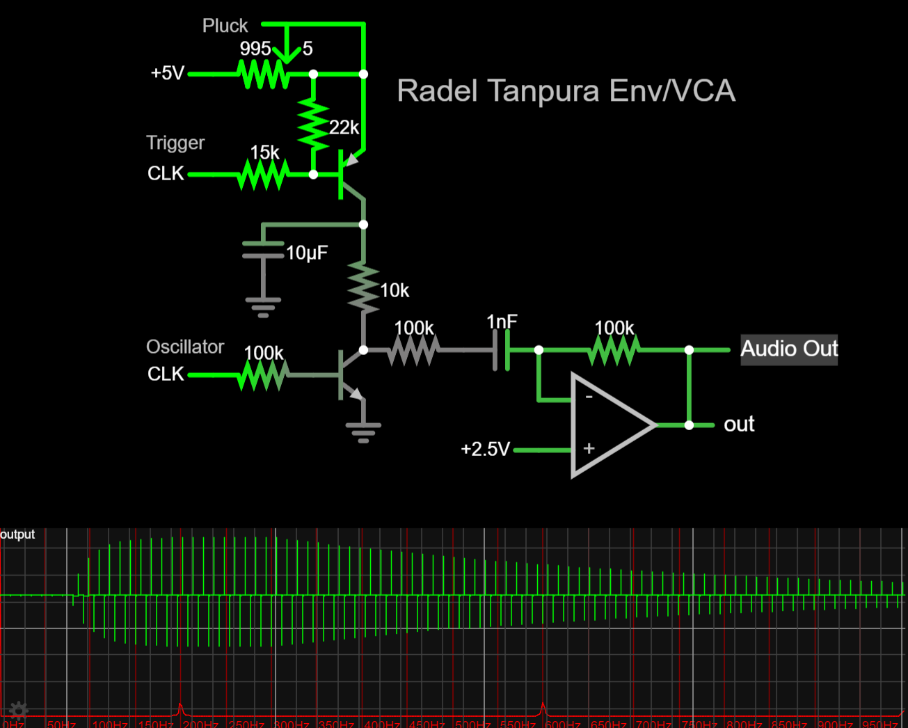
       Here's a schematic I drew from tracing the board, and probing for values. It turns out that it provides envelopes and VCAs.

Daughterboard schematic


    The PNP transistors charge the external electrolytic capacitors when they get triggers from the mainboard. The rate that they charge is controlled by a potentiometer labeled "pluck". A more conventional term for it would be "attack", as this is an envelope generator.
    The NPNs work as very crude VCAs. They pass the envelope voltage through when the oscillator is low, and they clamp the output to ground when the osc is high. This only really works because our oscillators are square waves. Other waveforms would be distorted.

    The outputs are unipolar, "reaching up" from ground. They need to be balanced equally around a reference voltage. This is achieved with the four capacitors on the board. They're part of four highpass filters that remove the DC offsets, along with other low frequencies.

    Here's a link to a Falstad simulation. You can listen to the output by allowing it to buffer, then clicking on the "Play Audio" button.


Recreation


    I used the schematics I drew to make a small clone of the instrument. I took some liberties, but it's mostly faithful. I made four daughterboards, one for each voice (osc, env, vca). Here's a short demo.
    

    I had some ideas about other ways the circuit could be implemented. Instead of highpassing the signal to make it bipolar, a portion of the envelope could be subtracted from the audio. Here's an example of the concept:

Balancing without filtering


    Some further reading and audio (of a similar model) is available at MatrixSynth courtesy of Loscha.

Saturday, April 27, 2024

Electro Harmonix EH400 Mini Synthesizer

 A friend asked me about adding CV and gate inputs to an Electro Harmonix EH400 Mini Synthesizer. Don't get it confused with their "Micro Synthesizer", "Micro Synth",  "Mono Synth", "Synth 9", etc.

I couldn't find all that much about the synth, or how to mod it, but there is a low quality scan of the schematic. It's hard to make out, and the layout obscures what the parts of the circuit are.

Original schematic

Of course I redrew it in Eagle CAD. I broke the circuit down into logical parts, laid them out in a more conventional way and labeled some signals.


Redrawn schematic

The Oscillator

The oscillator uses a single comparator and is based on a classic relaxation oscillator.
A comparator-based hysteretic oscillator - Wikipedia

It has some tweaks though. The osc can be turned on and off by applying a gate signal to D2. This is needed because there is no VCA; the oscillator has to be turned off to prevent it from droning.
The octave can be changed by toggling switch S1. It changes the configuration of the two timing caps from parallel to series. This gives a 2 octave difference between the positions.
The addition of D1 keeps the timing caps from being charged up by the R4/R5 voltage divider through R3 and R2. Instead, they're charged by an external voltage that goes through R1 and R2.

The Keyboard

This brings us to the CV generation circuit. The lefthand side of the circuit lets the user dial in a voltage that will be put through the keyboard's chain of resistors (represented by one resistor labeled "KEYBOARD"). This voltage sets the maximum pitch, and allows for tuning and pitch bend.
It's worth noting that the keyboard is made of metal foil and doesn't have conventional, mechanical keys.
When a "key" is pressed, the KEYBOARD-C node will connect to a node on the resistor ladder. This will send current through the intonation trimmer and on to the oscillator, charging the timing capacitors.
Pressing a key also puts a voltage across C4 where it can be seen by comparator IC1C. It gets compared to a divided version of the voltage that was put into the keyboard. Due to the divider, C4's voltage will always be the more positive signal when a key is being pressed. This generates a gate signal at the comparator's output.


The LFO and PWM

The LFO is based on the same circuit as the main oscillator, not that anyone would be able to tell from the original schematic. They call it "phasing", but it's really accomplishing pulse width modulation by comparing the LFO with the main osc.
The "phasing" adjustment is an odd one. It changes the switching points of the LFO. This changes both the period and amplitude of the LFO. The actual rate that the timing cap charges/discharges stays the same though (in terms of voltage/time).
If the switch is toggled, it stops being an LFO and instead delivers a constant CV. The potentiometer now adjusts this voltage, and the comparator acts like a crude unity-gain buffer.


Here are both switch states modeled separately. Falstad doesn't like to simulate the right one at high speeds and it results in the capacitor draining some before the comparator notices. This happens to turn it back into an oscillator.


The Filter

The original's filter looks especially tangled and odd. It makes more sense once you see that R29 and R37 form a voltage divider that's used as a reference voltage. That said, it's still odd.

There are two stages to the filter and they're in parallel. They have the same topology, but are tuned differently (C8/C10 vs C12/C15). Switch S5 can be used to disconnect the lower stage, and boost the upper one.

Both stages are built around CA3094 OTAs. These chips are typical OTAs that include a darlington pair that acts as a buffer. One unique feature is that all three terminals of the pair are exposed at pins 1, 8 and 6.


Here's the Falstad simulation. The buffer design is based off of the CA3094's datasheet.


The Envelope

The envelope is interesting because it uses a start and stop voltage instead of amount/offset. Unfortunately, it doesn't perform very well (at least in the simulation).
Q1 should be applying the start voltage to C6 when the gate signal is low, but C6 is always influenced somewhat by the stop voltage via R21.
When the gate is high, the start voltage is disconnected, and gives the stop voltage full control.
C6 is buffered by Q4 and sent to the current control pins of the filter stages.

There's also a piezo disc that generates a voltage when the keyboard is played forcefully. It gets buffered by Q3 and Q2 before being tied directly to the envelope's capacitor.


Leftovers

Maybe later I'll get into adding the CV control that started this. The simple answer is to add an exponential current source in place of the keyboard resistor ladder. I suspect that the oscillator's sluggish reset will cause the tuning to go flat at higher pitches though. 
It looks like a gate signal can be applied across C4 to recreate the signal from the keyboard.

The suboscillator is uninteresting as it's a simple d-type latch that's set up as a divider. The square output of the oscillator feeds into one half of the latch that seems to be used as a buffer, before going into the divider half.

There's also a 6V regulator built around a zener diode and a buffer transistor.

Lastly there's a speaker amplifier that isn't drawn, because it's not relevant to the synthesis.

Update

Revised files, including a board layout, have been added to github here.