Saturday, June 18, 2016

CZ 1000 Noise Fix (DAC Adjustment)

So I picked up an as-is CZ 1000. It started off terribly distorted, but after jumping a few corroded traces it started to sound more normal. Still not right though. Some presets had an odd harshness and some a "zipper" sound as they decayed.

It might not come across on soundcloud, but here's an example.


After some searching I found several people discussing similar problems. Each time the solution was to adjust the DAC's offset voltage. The schematics can be found easily and they depict the DAC portion like this:


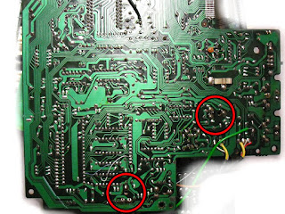
VR2 is the obvious candidate, but turning it had no effect. I started looking at the board and it turns out that there is another, less visible trim pot (VR4) up near the MIDI jacks. I can't even find it in the schematics, but once you get it in range (12 o'clock in my case), VR2 starts being helpful.

If VR2 is too far clockwise, you get more of the aliased "zipper" sound and too far counter-clockwise you get a more hissy/breathy sound. I can't find a specified voltage nor a test point for calibration, but I found it easy enough to calibrate by ear.

I had to take the CZ completely apart for other repairs. The screen had missing rows, but almost any HD44780 based LCD works as a replacement. Some buttons were unresponsive, but contact cleaner made them operable.
While I had it disassembled I took some photos of the trimmer locations. They're on the main board appropriately marked "M4152-MAIN".
To be clear, you only need to remove the bottom of the case to adjust things. Casio was nice enough to provide some holes so you can access the trimmers from the underside of the board.

Monday, June 13, 2016

DR 220 Mods

A while ago I had the opportunity to work on a friend's DR-220. Researching it I found a copy of the service manual, but not much else. I started experimenting with it and developed some relatively simple mods. I've already documented the sound ROM's format, but I never got around to the rest.

Here's a rough schematic of the parts I've added:
Starting at the top left, we have the trigger conditioners. They attach to the internal tom/kick triggers and regulate them to 5V 1ms trigger outs. For longer triggers R2/C2 and R15/C7 can be increased.

To the right there are two envelope generators. They replace the built in envelopes and allow you to change the decay and filter cut of the tom/kick. The envelopes are buffered by a TL072 that has to be run on the 9-12V rail. There wasn't enough headroom with the regular 5V rail.

Next is just the DB25 connector I used to attach the breakout box.

Below that is an ATTiny85. It accepts a slow, Volca-type clock input and produces a doubled clock with swing adjustment.

At the bottom left another Tiny85 and 4046 work as a new clock generator. I replaced the 2.4MHz crystal with a 74HCT4046 to allow CV pitch. I use the HCT line specifically since other logic families aren't rated in the multiple-megahertz range.
There is a catch with the new clock. The original circuit uses the ASIC to generate multiple clocks/timer interrupts for the CPU. When you over/underclock the ASIC, you affect the CPU. It can run over a decent range, but becomes erratic or unresponsive at extremes.
I chose to sever the clock connections and substitute the Tiny85 as clock gen.

Finally there is a simple buffer that allows for a separate out. This can be duplicated 6 times to provide 6 output groups.

Most of the components fit in the battery compartment and the rest went into the breakout box. Pictures below: