Showing posts with label Electro Harmonix. Show all posts

Saturday, July 19, 2025

Adding MIDI to the Electro Harmonix EH400 Mini Synthesizer

    Once again we return to the EH400. This time we're looking at adding MIDI.
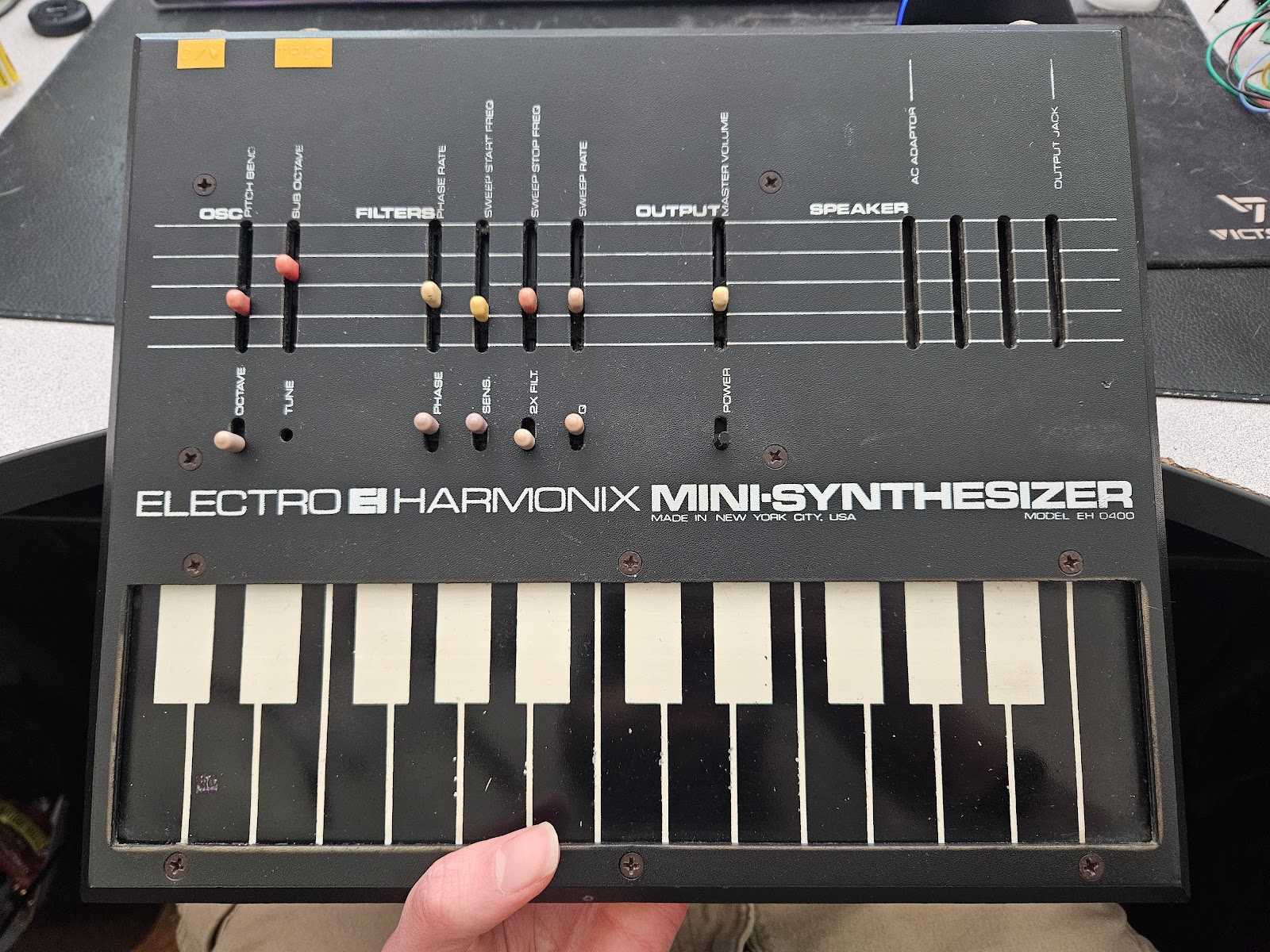
    This mod is for a friend and needs to retain the use of the original controls. While it's tempting to build on the CV mod from last time, that's not compatible with the original touch keyboard. We need to perform the functions of the keyboard, but we have an uncommon keyboard. It works by shorting the top foil of the keyboard to one of the 25 contacts on the lower PCB. This presents one of 25 different resistances to the oscillator, and causes a note to play. How can we fake this?

Resistance

    One way is to simulate this keyboard via some kind of variable resistance. It could be a digital potentiometer, or a DAC + a voltage controlled resistor. This problem is that this replaces the keyboard. This could be fixed by somehow switching between the original keyboard and the new resistance, or by reading the keyboard and using it to control the new resistance.

Push the Button

    A simpler solution is to control the keyboard directly, by pretending to press the "keys". We can short the foil to the pads via some kind of switch. BJTs, optocouplers, FETs, and analog switches are among the options. Considering we'll need 25 switches, we want something that's not too cumbersome. Analog switches are nice because you can get several of them in one package. Luckily, we don't need 25 completely separate switches; they'll all be sharing the foil as one of their terminals. This means we can use an analog multiplexer like the CD4051, as it has many switches with one common connection.

One of many

    It's important to pick the right multiplexer (mux) for the job. Ideally we'd find a 25:1 mux, but they really only come in powers of two, up to 16. To make things simple, we'd like it to run off of the 9V supply rail, and we'd like a low "on" resistance too. This keeps it from impacting the tuning too much. This narrows down our options to mainly derivatives of the CD4067. The 74HC4067 has a lower on resistance while still being able to tolerate the 9V supply. In practice, a normal CD4067 might be low enough though.

4067 multiplexer

Free range

    So, we can manage our 25 switches with two muxes. There's another component to controlling the pitch though, the octave switch. It shifts the keyboard by two octaves. We'll need digital control of this octave switch in order to have the full 4 octave range available over MIDI. How does this switch work though?

Front and back, and side to side

    There are two capacitors that dictate the range. One might assume that the switch selects between a larger one, and a smaller one, to change octaves. Turns out that they're both the same size though. It's their configuration that the switch changes. This is done because capacitors are somewhat low tolerance devices. Let's say they're 5%; one cap could be +5% while the other is -5%. That puts them pretty significantly out of tune with each other. Instead, the circuit uses the fact that caps in parallel sum together, and caps in series decrease in value. The math behind this turns out to work in our favor.

Series vs parallel from wiki.testguy.net

    Parallel is simply C1 + C2, but series is (C1 * C2)/(C1 + C2). Let's plug in some worst case scenario 5% 100nf capacitors: (105nf * 95nf)/(105nf + 95nf) = 9975/200 = 49.875nf series. 105nf + 95nf = 200nf parallel. 49.875nf vs 200nf. Wow, we're only a quarter of a percent out from a perfect four-to-one relationship (two octave shift). So, this change in configuration (parallel vs serial) gives a result that brings our octaves much closer to in tune than 5% capacitors would normally allow.

Another one

    We find that we need one more analog switch to control the parallel/serial capacitor configuration. This time we don't need 16 throws, but the on resistance is especially important. There are a number of candidates, but the DG409LEDY happens to be relatively cheap and available at the moment. It's a dual 4:1 mux that can handle the voltage and is rated at 17Ω on resistance.

    A simple solution would be to copy the connections of the original, mechanical switch. "On resistance" wasn't a consideration in its design though. It's important that we chain as few connections through the switch as possible, so that we don't keep stacking this 17Ω penalty. Here's one arrangement that limits this while still switching between serial and parallel.

Octave switch - Simulate here


The soft side

    As with any MIDI project, there's software and digital IO involved. This opens up new possibilities on a synth that was completely analog. We can control things remotely, generate new signals, or respond to new inputs. Given how spartan the synth is, there are only so many targets for modulation. The filter and the oscillator are the big ones.
Arduino Pro Mini

Lasting impact

    There's one more thing that the original keyboard offers, a form of velocity labeled "Sense". This is accomplished with a piezo that's stuck to the bottom of the keyboard, and routed into the envelope generator. We can take our MIDI velocity, turn it into a voltage, and pipe it into the same point. This is far from precise work, so we can generate our voltage in an imprecise way: pulse width modulation. Many microcontrollers have provisions to generate PWM and it can easily be filtered into a useable voltage.

Notes between notes

    We can fairly easily add a feature that that original instrument lacked: portamento. This is a smooth sliding effect between notes. Just one problem, we're stuck with the rigid notes we have. But, glissando done fast enough approximates the sound of portamento. This means playing every note that falls between the previous and current note. This could be as little as zero notes, or all four octaves of notes. The effect is most convincing when done quickly and over a large range. It doesn't require any extra hardware though, just code to change notes.

Other thoughts

    Key tracking could be added without too much trouble, as could other software modulation sources like LFOs, or envelopes. The only obvious destinations are the filter and the pulse width setting. These already have an envelope and an LFO respectively though.

    Key retriggering could be forced on by resetting the envelope during every note on. This would disable the legato behavior of the original keyboard.

    Some cross modulation would be possible with the addition of VCAs or digipots. The filter could be FM'd by the oscillator, or the oscillator could be AM'd by the LFO. At some point you lose the spirit of the original instrument though.

Closing circuit

A one-off MIDI board

EH400 MIDI schematic

Files

    The source code and schematics for this MIDI retrofit are available on Git Hub, here. It's intended to be built with an Arduino Pro Mini, but small changes will allow it to run on many AVRs.

Demo


    You can also hear the synth used in a few actual songs:

Bliss - Stomp

Van Halen - Sunday Afternoon in the Park


Saturday, August 10, 2024

Adding CV to the Electro Harmonix EH400 Mini Synthesizer

    This is a follow up to our previous look at the EH400 here. Now we're investigating methods of voltage controlling the oscillator.

    As a reminder, this is what we're up against. It's similar to a relaxation oscillator, but it's been modified to charge through a resistance labeled "keyboard".

The original oscillator circuit

Get your VCRs ready

     One approach to adding CV would be to replace the resistor with some kind of voltage-controlled resistor (VCR). These circuits are a bit uncommon though. Another difficulty would be figuring out the relationship between resistance and frequency, then replicating it in the VCR. The saw recharges quite slowly because of R2, and this impacts the relationship.

Update

    I decided to graph the resistance that corresponds to each of the 24 note (1 being the lowest, 24 being the highest). With the help of a curve fitting tool and Wolfram Alpha, I ended up with this formula: resistance(k) = 188.198 - 44.8472 * e^(0.0574576 * note)

Current affairs

    We can do away with the resistance worries by instead forcing a current into the timing capacitor C2. We could then use a much more conventional voltage controlled exponential current source, instead of a VCR. This is a circuit that's very common in synthesizers, and will give us a standard 1 volt per octave response, while also being relatively temperature stable.
    There are some voltage requirements that make the oscillator a little hard to current control though. The cap needs to swing from 2V to 4V. The typical expo source can't do this directly, but we can add a current mirror to help it along.
    Here we've added a standard expo source (actually a current sink). We've also lowered R2 to 1k to help mitigate the slow recharge time.


Expo sink and current mirror design

    This mostly works, but the tuning goes flat on the low end. I'm unsure what to blame this on, maybe the current mirror. Regardless, it's back to the drawing board.


Derivation

    Part of the trouble with this oscillator is that it's too different from typical VCOs. How can we bring it more in-line without replacing it entirely? Well, we have to look at it differently. What we've been calling a "modified relaxation oscillator" can also be thought of as a variation on a schmitt trigger.


Schmitt Trigger

    The majority of VCOs have a schmitt trigger in them somewhere, and many of them are related to this schmitt + integrator design:


    By adding an integrator we can turn this into a more normal oscillator, one that lends itself to being voltage controlled. We only have to make minimal changes to the original board to accomplish this. The original timing cap needs to be removed, and the integrator needs to be connected in its place. If we want to replicate the original's sawtooth waveform, we can tap the "pulse" output and use it to reset our integrator. As a bonus, this resets much faster than the original oscillator did, and pretty much cures the slow reset problem. Now we have a fairly conventional oscillator.


Sinking lower

    With our new oscillator design, the exponential current sink becomes more useful. It doesn't have to make the capacitor swing to any voltage, not directly anyway. The integrator does all the work, while presenting a relatively constant voltage to the current sink.

    Since the integrator is the one charging the cap, it does have to worry about the voltage swing. It must reach both 2V and 4V. If we run it using half of VCC as our AGND, then we'll run into a problem on reset. The reset pulse will only bring it down to 6V/2 = 3V, and not the 2V that we need. This is because the reset pulse "closes" T3 and turns the op-amp into a unity gain buffer. This effectively forces the AGND voltage (from the non-inverting input) to show up at the output.

Unity gain buffer

    We can fix this by lowering our AGND voltage to below 2V. We just need to play with the values in a voltage divider until we come up with something that's a safe margin below 2V. Our 6V supply into 33k + 15k yields 1.875V.

    Here it is all put together. Conveniently, it only requires one quad op-amp to add the expo sink, integrator, and buffers. Falstad link here


The complete CV circuit


Saturday, April 27, 2024

Electro Harmonix EH400 Mini Synthesizer

 A friend asked me about adding CV and gate inputs to an Electro Harmonix EH400 Mini Synthesizer. Don't get it confused with their "Micro Synthesizer", "Micro Synth",  "Mono Synth", "Synth 9", etc.

I couldn't find all that much about the synth, or how to mod it, but there is a low quality scan of the schematic. It's hard to make out, and the layout obscures what the parts of the circuit are.

Original schematic

Of course I redrew it in Eagle CAD. I broke the circuit down into logical parts, laid them out in a more conventional way and labeled some signals.


Redrawn schematic

The Oscillator

The oscillator uses a single comparator and is based on a classic relaxation oscillator.
A comparator-based hysteretic oscillator - Wikipedia

It has some tweaks though. The osc can be turned on and off by applying a gate signal to D2. This is needed because there is no VCA; the oscillator has to be turned off to prevent it from droning.
The octave can be changed by toggling switch S1. It changes the configuration of the two timing caps from parallel to series. This gives a 2 octave difference between the positions.
The addition of D1 keeps the timing caps from being charged up by the R4/R5 voltage divider through R3 and R2. Instead, they're charged by an external voltage that goes through R1 and R2.

The Keyboard

This brings us to the CV generation circuit. The lefthand side of the circuit lets the user dial in a voltage that will be put through the keyboard's chain of resistors (represented by one resistor labeled "KEYBOARD"). This voltage sets the maximum pitch, and allows for tuning and pitch bend.
It's worth noting that the keyboard is made of metal foil and doesn't have conventional, mechanical keys.
When a "key" is pressed, the KEYBOARD-C node will connect to a node on the resistor ladder. This will send current through the intonation trimmer and on to the oscillator, charging the timing capacitors.
Pressing a key also puts a voltage across C4 where it can be seen by comparator IC1C. It gets compared to a divided version of the voltage that was put into the keyboard. Due to the divider, C4's voltage will always be the more positive signal when a key is being pressed. This generates a gate signal at the comparator's output.


The LFO and PWM

The LFO is based on the same circuit as the main oscillator, not that anyone would be able to tell from the original schematic. They call it "phasing", but it's really accomplishing pulse width modulation by comparing the LFO with the main osc.
The "phasing" adjustment is an odd one. It changes the switching points of the LFO. This changes both the period and amplitude of the LFO. The actual rate that the timing cap charges/discharges stays the same though (in terms of voltage/time).
If the switch is toggled, it stops being an LFO and instead delivers a constant CV. The potentiometer now adjusts this voltage, and the comparator acts like a crude unity-gain buffer.


Here are both switch states modeled separately. Falstad doesn't like to simulate the right one at high speeds and it results in the capacitor draining some before the comparator notices. This happens to turn it back into an oscillator.


The Filter

The original's filter looks especially tangled and odd. It makes more sense once you see that R29 and R37 form a voltage divider that's used as a reference voltage. That said, it's still odd.

There are two stages to the filter and they're in parallel. They have the same topology, but are tuned differently (C8/C10 vs C12/C15). Switch S5 can be used to disconnect the lower stage, and boost the upper one.

Both stages are built around CA3094 OTAs. These chips are typical OTAs that include a darlington pair that acts as a buffer. One unique feature is that all three terminals of the pair are exposed at pins 1, 8 and 6.


Here's the Falstad simulation. The buffer design is based off of the CA3094's datasheet.


The Envelope

The envelope is interesting because it uses a start and stop voltage instead of amount/offset. Unfortunately, it doesn't perform very well (at least in the simulation).
Q1 should be applying the start voltage to C6 when the gate signal is low, but C6 is always influenced somewhat by the stop voltage via R21.
When the gate is high, the start voltage is disconnected, and gives the stop voltage full control.
C6 is buffered by Q4 and sent to the current control pins of the filter stages.

There's also a piezo disc that generates a voltage when the keyboard is played forcefully. It gets buffered by Q3 and Q2 before being tied directly to the envelope's capacitor.


Leftovers

Maybe later I'll get into adding the CV control that started this. The simple answer is to add an exponential current source in place of the keyboard resistor ladder. I suspect that the oscillator's sluggish reset will cause the tuning to go flat at higher pitches though. 
It looks like a gate signal can be applied across C4 to recreate the signal from the keyboard.

The suboscillator is uninteresting as it's a simple d-type latch that's set up as a divider. The square output of the oscillator feeds into one half of the latch that seems to be used as a buffer, before going into the divider half.

There's also a 6V regulator built around a zener diode and a buffer transistor.

Lastly there's a speaker amplifier that isn't drawn, because it's not relevant to the synthesis.

Update

Revised files, including a board layout, have been added to github here.

Wednesday, March 18, 2020

Electro Harmonix Rhythm 12 Schematic

I was able to get another obscure drum machine, an Electro Harmonix Rhythm 12.
It has a somewhat unique sound, and I wanted to understand the voices better. There is a schematic available out there, but it's not the clearest. As usual, I decided to redraw it in Eagle CAD.

There are basically 4 voices, but they can be manipulated a bit. Parts of the sounds can be muted or even cut short.

Here is the portion that actually creates the sound. The sequencing and amplification parts are not shown. 

There are four "Twin-T" oscillators present. Three are damped, so that they decay naturally. One is self oscillating, and generates a tone used in the cymbal.

The cymbal and snare noise go through single transistor VCAs. These are pretty crude, and seem to work by offsetting the input into (and out of) the active region of the transistor. This heavily distorts the signal, but it does work.


Most of the other transistor serve to mute drums for pattern variations.

Here is the beginning of a layout. It's very easy to route, and could be done single-sided with some jumpers.