Showing posts with label Korg. Show all posts

Sunday, March 10, 2024

Korg Monotron Oscillator Sync

    I developed this mod specifically for the Montron Duo, so that one oscillator could sync to the other. Since all three models of Monotron share the same oscillator design though, the mod is applicable to them all. Here we'll look at the original model.

    The crux of syncing is resetting an oscillator, but not every oscillator lends itself to being reset. I also wanted to avoid heavily modifying the Monotron board. That means limiting things like cutting traces, lifting legs, removing/replacing components.

    Here's the VCO we have to work with, taken from the Monotron schematic. It's a saw-core that uses a couple schmitt triggers and a transistor for the charging phase, plus a current sink for the discharge phase. Q2 is constantly discharging the timing capacitor, C11. Meanwhile, the schmitts watch the voltage of C11. When it gets too low, they recharge it through Q5. The built-in thresholds of the schmitts define when they start and stop this recharging stage. 

    This "recharge" is a method of resetting. So, the oscillator already has an internal reset signal and reset mechanism.

Monotron VCO

Korg's Sync Circuit

    We need look no further than the LFO to find an actual sync circuit (though they call it "reset"). The LFO is essentially the same as the main oscillator, just with this sync circuit added.

Monotron LFO with sync circuit highlighted

    I've created a version of the LFO in Falstad's Circuit Simulator, link here. I've renamed the input to "Sync", and the internal pulse to "Reset Pulse" on the trace below.

    When the sync pulse goes high, Q8 pulls the input of the first schmitt low, as if the capacitor's charge was low. This forces the circuit into the recharge stage. Q7 pulls the second schmitt low, and delays the recharge until the sync pulse goes low. This is enough to sync the LFO.

Simulated LFO

    While this is promising, there is a catch. The reset circuit inserts resistors R33 + F1 before schmitt one, and R32 between the schmitts. This would require some fiddly trace cutting if we were to apply it to the VCO.

My Sync Circuit


    I took a different approach, and tried to discharge the capacitor using the sync pulse. This can be done with just an NPN transistor. We have to be careful about how much we discharge the capacitor though. A naive approach might discharge the cap below the point that it should begin charging again, changing the pitch and amplitude.

    We can prevent this overshoot by checking the output of the second schmitt. While it's high, we're safe to discharge. Once it goes low, we've hit the lower threshold, and it's time to stop. If we AND this signal with our sync pulse, we can safely limit how much the capacitor will discharge. We also get a free sync enable/disable input if we use a three-input AND.

New sync circuit


    This works well in practice, but there are limitations. 

    If the sync pulse is too long, it will extend past the capacitor recharging stage, and force it low again. This will keep it cycling rapidly until the sync pulse stops, and produce a high pitched tone.
    If the sync pulse is too short, the capacitor won't fully discharge before the pulse ends, and the oscillator won't reset.
    So, the ideal length for the sync pulse would be exactly long enough to discharge the capacitor.

    Keep in mind that the capacitor is always being discharged based on an ever-changing pitch voltage. The capacitor will also be charged to an arbitrary voltage when we try to reset it. This means that the discharge time is a moving target, and there is no one perfect sync pulse length.

    We can fix this by adding a set-reset latch that will catch the edge of the sync pulse, stretch it out to the right length, and end it once the capacitor is fully discharged. Here's an exaggerated trace to demonstrate the concept.

Latched sync pulse example


Here's is the Falstad link for the latched version

Latched sync circuit


    The sync pulse sets the latch, which starts discharging the capacitor. Once it discharges to the lower limit, the second schmitt will go high, resetting the latch, and allowing the capacitor to recharge.
While the non-latched circuit might be good enough, this circuit will work across a much broader range of frequencies.

Monday, February 19, 2024

Korg Monotron Duo modifications

    I've been experimenting with Monotrons since around the time of the original's release. I took an interest in the Duo model more recently though. The extra oscillator opens up some modulation options, and paraphonic possibilities. I thought it would be fun to digitally control as many parameters as possible. 

    After experimenting with using OTAs to control things, I determined that digital potentiometers would be easier. Unfortunately, there has been an ongoing shortage with the digipots that the project calls for. Because of this, the project has been shelved for some time. While working on this, I developed some modifications that don't require digipots though: 

  • Oscillator sync
  • XOR ringmod
  • Squarewave anding
  • Sub oscillator
  • PWM 
  • filter HP input
  • VCF crossmod

    I'm posting now to at least keep the schematics from sitting on my hard drive. I hope to follow this up with a breakdown of each mod.


Full schematic


Wednesday, October 19, 2022

Tuesday, March 29, 2022

Korg Monotron PCB Component Labels

     I've been interested in modifying a Korg Monotron. I found a labeled PCB image at Tim Stinchcombe's site here. I found the red labels very difficult to read though, so I did a little editing in Gimp. Here's the resulting image.

more legible PCB labels


Thursday, May 7, 2020

Korg Monotron Delay PCB Component Labels

Even though it's old-hat, I'd like to try modifying the Korg Monotron Delay.
Korg was nice enough to share their schematic, but not the board layout. Also, the board itself isn't labeled.
I need to know what I'm working with, so I used a multimeter, and some educated guesses to draw the following. I labeled the rough sections of the circuit, so that it's a little easier to find what you're looking for. Be warned that it's not perfect, but should be a decent starting point.

Saturday, April 11, 2020

Korg KR-55 Recap Guide

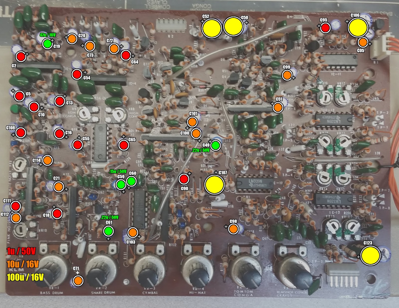
I'm repairing my second Korg KR-55 drum machine. They both had a ton of failing electrolytic capacitors that needed replacing. In the first machine, the capacitors had leaked and damaged the board. In the second, one had failed and shorted, causing the snare, hihats, and cowbell to not work.

Recommending "recaping" as a general fix, is something of meme now. It's no joke on the Korgs though. I advise replacing all the electrolytics in them, so I made a the following images and lists to help.

The logic board only has a few capacitors. The 470u are the large, axial type, and don't seem to be an issue. They're listed for completeness.
Name Value Voltage
C21 .33u 50V
C1 10u 16V
C22 470u 25V
C23 470u 25V

Here are the relevant capacitors on the sound board. They're color coded by value.
Red = 1u / 50V
Org = 10u / 16V
Ylw = 100u / 16V
Grn = other

Here are the footprints on the bottom, to help with desoldering. These are not coded, because they should all be removed.

Here are the types and totals of capacitors:
Value Voltage Total
.15u 50V 2
.22u 50V 2
100u 16V 5
10u 16V 14
1u 50V 14
47u 16V 1

Here are the individual capacitors, and their function in the circuit. This can be helpful for debugging.
Name Value Voltage Role
C59 .15u 50V Low Conga
C60 .15u 50V Hi Conga
C49 .22u 50V HiHat
C61 .22u 50V Tom Noise Audio
C50 100u 16V Cymbal Power
C52 100u 16V Hat Power
C106 100u 16V Power
C107 100u 16V Power
C123 100u 16V Metal Power
C20 10u 16V Bd, Sn Power
C21 10u 16V Bd, Sn Power
C51 10u 16V Cymbal Power
C71 10u 16V Tom/Conga Audio
C72 10u 16V Tom/Conga Power
C73 10u 16V Tom/Conga Power
C98 10u 16V RS/Clav/CB Audio
C99 10u 16V RS/Clav/CB Power
C100 10u 16V RS/Clav/CB Power
C101 10u 16V RS/Clav/CB Power
C103 10u 16V Mix Audio
C105 (C05) 10u 16V Power
C112 10u 16V Noise
C114 10u 16V Noise Power
C2 1u 50v Bd Trigger
C5 1u 50v Bd Audio
C10 1u 50V Sn
C13 1u 50V Sn Audio
C16 1u 50V Sn Body Audio
C18 1u 50V Sn Audio
C54 1u 50V Low Conga
C55 1u 50V Low Conga
C64 1u 50V Hi Conga
C65 1u 50V Hi Conga
C90 1u 50V Claves Audio
C95 1u 50V Cowbell
C108 1u 50V Noise
C111 1u 50V Noise
C19 47u 16V Bd, Sn Power

Saturday, September 16, 2017

Korg Nanokontrol Schematic + New Firmware

Ages ago I drew a schematic for Korg's original Nanokontrol. I finally decided to dust it off and do something with it.

From the outside the Nanokontrol is just a USB control surface, but inside it hides an AVR microcontroller. It even has the ISP (programming) header broken out, though the pinout differs. With this it seems pretty natural to write a new firmware for it.

I wanted a simple project that demonstrates interfacing the potentiometers, LEDs and buttons. The idea of a CV step sequencer sprang to mind. In order to get nice clean voltage output I decided to add a DAC. The problem with adding to this setup is the general lack of IO pins. The serial pins TX and RX are conspicuously unused, but I chose to leave them free for possible MIDI communication. I don't plan on using USB MIDI, so I freed up IO by removing the USB chip.

PDIUSBD12 USB chip
The USB chip actually serves as the clock source for the AVR, so a replacement clock must be supplied. Step one is to flash the AVR fuses such that it can accept a crystal clock source. This has to be done while we still have an external clock. After that the USB chip can be removed and a crystal can be attached to the XTAL pins of the AVR. Conveniently the USB chip has an external crystal footprint that we can repurpose.

Now most of IO PORTD is free to use. I used one external interrupt pin for the trigger input. This makes it fast and easy to step the sequencer in response to an external clock/trigger. This leave plenty of pins for the DAC (MAX528). It gets its own clock and chip select lines, but it shares the data line with the LED shift register since it's clocked separately.

This is what the schematic looks like after the modifications:

Modified Nanokontrol
This setup works, but the CV output only spans about 0-4V. To broaden this, the DAC can operate on +12V while still responding to TTL level control. It just needs the supply rail and reference voltages changed to 12V. For convenience sake, I also added a 5V regulator. This makes it easy to run the entire setup off of 12V.

MAX528 12V configuration
Now all of the hardware modifications are done. It's time to write some code. The only trickiness comes from interfacing the multiplexed IO. Here is an overview of how to read/write them:

Read Buttons:
  1. Pull PC0-3 low one at a time to enable one column
  2. Pull PC4 low to enable buffer
  3. Read PINB for button statuses (low = pressed)
  4. Repeat steps 1-3 pulling each column low

Read Pots:
  1. Set PA0-2 to select pot from Mux
  2. Read Mux on PA4 and PA6
  3. Read single pots on PA5 and PA7
  4. Repeat steps 1-3 selecting each set of pots

Write LEDs:
  1. Set PC7 high to disable LED output
  2. Write first bit to PD7 (low to turn on)
  3. Set PA3 high, then low to clock in bit
  4. Repeat steps 1&2 for all 8 bits
  5. Set PC5-7 to select column and enable LED output
  6. Delay to allow LEDs to shine
  7. Repeat steps 1-6 selecting each column

The code and schematics can be found on my github here. The code is pretty barebones and simple. It just serves to demonstrate interfacing the Nanokontrol hardware. There are some obvious upgrade and features that can be added, so this is just a starting point.