Showing posts with label Technical Doc. Show all posts

Sunday, September 11, 2016

Pearl DRUM-X Schematic

Pearl's DRUM-X is a somewhat overlooked, five voice, analog drum synthesizer. It's intended to be connected to drum pads, similar to the old Simmons SDS line.

I'm generally interested in analog drums, so I wanted to try understanding the design. Unfortunately, there doesn't seem to be a copy of the schematic anywhere. So, I took some photos of the board and pieced together a schematic. The five voices are nearly identical, so only redrew one. Here it is:


To give a general summary, each voice has 3 VCOs, 1 Lowpass VCF, 2 Envelope generators and 5 VCAs

If you compare schematics, it looks like it evolved out of the Syncussion. The strange transistor-pair and CMOS inverter clusters have been (mostly) replaced with more normal OTAs. Some portions of the schematics are still nearly identical. The envelope generator and final VCA for example.

Another part of the evolution is the presence of CMOS bilateral switches. When switched at a high frequency, they act as duty-cycle controlled resistors. If switched by a VCO with voltage controlled duty-cycle, they act as voltage controlled resistors.
There are two 4016s per voice, used to voltage control the various VCO pitches and filter cut. Strangely, they are run on a +5V rail, while the rest of the system runs on ±8V.


VCOs

There are three identical, but differently tuned VCOs. One is the regular, fundamental tone of the drum. Two serve to generate the "overtone" signal, a somewhat atonal sound that can be mixed with the fundamental.

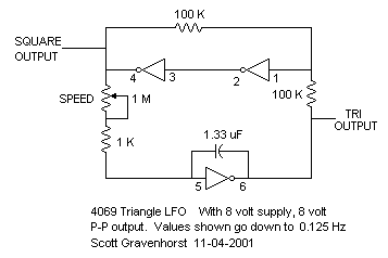
The VCOs are a pretty standard 4069 square/triangle oscillator design. In this case, only the triangle output is used. Most designs include a potentiometer for pitch adjustment. These instead use a 4016 switch to implement voltage control. They cannot be tuned separately due to sharing the same CV signal.


VCAs

All but the main VCA use the same LM13700 design. It's the bare minimum, leaving out the buffer and bias diodes. Here it is compared to the example from the datasheet:


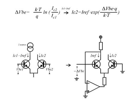
The transistor pairs driving them are more interesting. I've only ever seen them in hand clap circuits. They form a differential pair, but are biased to be an exponential current source.


The transistor pairs driving the "Attack VCA" and "Over-T VCA" (pairs T1 and T4) are also acting as VCAs themselves. They're multiplying the CV at the base with the Envelope CV coming in the emitter. This allows voltage control over the volume without changing the envelope.

The pairs driving the "VCO/Noise Bal" are opposites of each other. That is to say, one pair is inverting and the other is non-inverting. This lets one CV signal mix the VCO and Noise signals relative to each other.

Over Tone VCA

This VCAs serves to mix out the over tone signal based on the main envelope. This gives more over tone signal at the start of the sound and less at the tail.

Attack VCA

This VCA lets in a quick burst of noise to simulate a real drum transient.

Main VCA

The main VCA is a differential pair + current source. It uses a variation on an exponential converter to multiply the volume CV with the main envelope and drive the main VCA.

Envelope Generator

This is a decay-only envelope generator. C20 is the core of it. It's charged by a trigger through T5 and drained by Q2.

Transistor pair Q2 and Op-Amp IC6B also look like a variation on an exponential convertor. They serve as a current sink to voltage control the draining of C20(decay).

T6, C22 and R55 form a second, simpler envelope generator. It works the same way, minus voltage control.

VCF

There is only one VCF per voice. The entire mix is passed through this filter before hitting the main VCA.

It's a standard Sallen-Key low-pass filter. The resistive elements are realised with more 4016 switches. IC15B biases it to a virtual ground sitting at +2.5V. This is so the signal falls within the 4016's supply rails.

4016 CV

As I've said, the 4016 switches need to be given a duty-cycle (PWM) signal to change their resistance. This is accomplished by generating a sawtooth wave (labeled PWM_4016) and comparing it to a CV signal.

For example, the filter CV (FLT_CV) is fed into buffer IC8C, passively mixed with the main envelope and biased toward the positive rail. This signal, along with our sawtooth are fed into comparator IC4B and output to the 4016.

When the CV signal is higher than the sawtooth, the output is high. When the CV is lower than the sawtooth, the output is low. This page demonstrates it nicely with this image:

The result is a pulse-width modulated wave that reflects the incoming CV.

CV Mux

The control logic (not pictured) generates CV signals and multiplexes them over one connection: MUX_CV. The CV's destination is defined by signals 4051_A, B and C.

The CV Mux circuit de-multiplexes the CV signals from the control logic. It select the output that corresponds to the 4051 signals and connects it to the incoming CV signal. This charges a capacitor at the output. Once the multiplexer moves on to the next output the previous output goes hi-Z. This prevents the multiplexer from draining the capacitor and allows the capacitor to retain its voltage.

In this way, the multiplexer is also a multi-output sample and hold, grabbing voltages and holding onto them.


Noise

The noise circuit is part of the control logic, so is not pictured with the rest. It's built around a reverse biased 2SC1815 NPN transistor, similar to the 808's. It's lowpass filtered before being sent to the separate voices.


Odds and Ends

There are some unconnected and strangely arranged components. I'm guessing these are utilised in the other voice configurations.

The most obvious one is IC13 (4016). It has two switches connect to the attack VCA's output and not much else. They look like the start of a sallen key high-pass filter, but there's no op-amp connected to them.

Here is a block diagram of one voice:


The full schematic images and eagle files are on my github here.

Saturday, October 10, 2015

DR 220 ROM

The DR 220's ROM is partially audio data and partially pattern/miscellaneous data.

The 220 comes in two flavors: 220A(coustic) and 220E(lectric). Most of the differences can be toggled and are contained in the gate array(IC1). The rest are in the sound ROM(IC2).

I haven't bothered breaking down the data portion since it doesn't appear to contain anything too interesting. Some simple tests suggest that it holds pattern/song data, instrument names for the lcd and instrument volumes. The volumes can be increased beyond what the normal interface allows, but it's buggy and can distort.

The audio is encoded as mono, signed, 8bit-packed, 12bit mu-law PCM @ 25KHz. A partial departure from the Roland standard.

None of the address lines nor data lines are jumbled and no samples are interleaved. It's pretty straightforward. Mu-law encoding is the big hurdle.

Mu-law is a logarithmic encoding that was used on some older drum machines: Linn, Oberheim, etc. The idea of it is to exploit our non-linear perception of sound. The encoding gives more precision to lower(quieter) amplitudes that we have better perception of. Conversely is has to remove some detail from higher(louder) amplitudes that we can't discern as well. It's a tradeoff for the more "valuable" part of the signal.

The nuts and bolts of the encoding work like scientific notation. Each number gets translated into a significand(mantissa) and an exponent. In the 220's case, the four least significant bits of each byte are the mantissa, the next most significant three are the exponent and the most significant is the sign bit. For whatever reason, the sign bit is nonstandard for mu-law. If the bit is set the byte must be inverted before being decoded.


TR-505 ROM

The TR-505 is very similar to the 626. Same sound chip, same general design.

The audio is encoded as 8bit, mono, linear PCM @ 25Khz. Standard Roland fare.

The sound ROM(IC11) has a smattering of jumbled data and address lines that makes it hard to read/write. Most of the pins can be unscrambled in software but, the actual chip(TC531000P) has a non-standard pinout. Its A16 is where most 28pin chips have an output enable line. A little rewiring is required to read it and a larger chip is required to duplicate it.

Even with the pins in order, the sounds are still scrambled. The short interleaved samples and the long chunked-up samples are sorted just like the 626, so I'll just reiterate a bit.
The short samples are combined: one sound on the odd addresses and one sound on the even addresses.
The long samples are put into "piles": A,B,C,D. Each pile contains every fourth byte. A has every fourth byte starting from 0, B has every fourth byte starting from 1, C every 4th from 2, D 4th from 3.

As one final point of confusion, A0 is inverted. Some basic glue logic was used to generate A0 (and A13-A16) and it was probably just easier to invert A0 in the ROM rather than invert the signal. Based on the binary I've found, no other address lines are inverted.

Here is the ROM table from the service manual.

TR-626 ROM

The 626's ROM is entirely audio data. Its data bus is wired directly to an R2R DAC and nothing else.

The audio is encoded as 8bit, mono, linear PCM @ 25KHz. This is a standard used by a few Roland machines: 707, 505, etc.

It's the simplest audio encoding and the ROM is effectively a WAV file without the header. Audacity can import it as an 8bit, unsigned, mono "raw binary". If you try this you'll find some recognizable drum sounds, but lots of static and strange noises.

The trouble comes from how the address lines are ordered and manipulated. First off, address lines 6 & 8 are swapped. Since the board is single sided, this was probably done for layout purposes.

The rest of the problems stem from the fact that two gate arrays control different portions of the address bus. IC14 (MB63H114) handles lines 1-12(A1-A12). IC13(MB671189PF) has A0 and A13-A17.

Some of the shorter samples are "interleaved", one sample on the odd addresses, the other on the even. IC13 forcing A0 constantly low(or high), while A1-A12 count normally, will select one of the two samples.

The longer samples (cymbals) are fragmented into 8k chunks. With some experimenting, I found that these chunks are just the opposite of the interleaved samples. They are ordered like dealt cards: 1 card(byte) for hand(chunk) A, 1 byte for chunk B, 1 for A, 1 for B, etc.
So, if you pick the bytes alternately, you'll get the original sample.

The service manual actually explains that this is the result of a kind of "retcon". IC13 is there to give IC14 access to a larger ROM. IC14 was not designed with this in mind. IC14 stops counting up once it reaches its max value of 2^12. IC13 gets around this by assuming the role of the least significant bits(the bits that count up the fastest) and making IC14 count the more significant, "slower" bits. By the time IC14 counts up to 2^12 the combination of IC13 and IC14 has actually counted up to, say, 2^14.

The service manual also gives us a nice table with some confusing naming conventions. The negative address lines indicate that you shift all the other lines left to make room. The A0 column serves to show if a sample is on the odds or evens.