A friend was generous and patient enough to lend me his Radel Tanpura (tambura) so I could reverse engineer it.
The Mainboard
The mainboard is pretty straightforward. It uses a 555 as a clock to feed a johnson counter. Outputs of the counter are tapped to serve as triggers for four voices. The voices are also built around 555 timers. At the end of the audio chain is a filter with speaker amplifier.
 |
| Mainboard schematic |
The Daughterboard
In between the oscillators and the filter is a curious daughterboard. It's a hybrid integrated circuit similar to the cards of a Roland Juno-106. It's also potted in some kind of epoxy, and had to be soaked in acetone before reverse engineering. Here it is with most of the orange coating removed.
 |
| Daughterboard PCB |
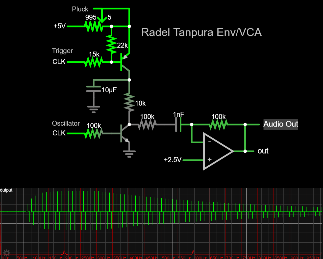
Here's a schematic I drew from tracing the board, and probing for values. It turns out that it provides envelopes and VCAs.
 |
| Daughterboard schematic |
The PNP transistors charge the external electrolytic capacitors when they get triggers from the mainboard. The rate that they charge is controlled by a potentiometer labeled "pluck". A more conventional term for it would be "attack", as this is an envelope generator.
The NPNs work as very crude VCAs. They pass the envelope voltage through when the oscillator is low, and they clamp the output to ground when the osc is high. This only really works because our oscillators are square waves. Other waveforms would be distorted.
The outputs are unipolar, "reaching up" from ground. They need to be balanced equally around a reference voltage. This is achieved with the four capacitors on the board. They're part of four highpass filters that remove the DC offsets, along with other low frequencies.
Here's a link to a Falstad simulation. You can listen to the output by allowing it to buffer, then clicking on the "Play Audio" button.
Recreation
I used the schematics I drew to make a small clone of the instrument. I took some liberties, but it's mostly faithful. I made four daughterboards, one for each voice (osc, env, vca). Here's a short demo.
I had some ideas about other ways the circuit could be implemented. Instead of highpassing the signal to make it bipolar, a portion of the envelope could be subtracted from the audio. Here's an example of the concept:
 |
| Balancing without filtering |