Pearl's DRUM-X is a somewhat overlooked, five voice, analog drum synthesizer. It's intended to be connected to drum pads, similar to the old Simmons SDS line.
I'm generally interested in analog drums, so I wanted to try understanding the design. Unfortunately, there doesn't seem to be a copy of the schematic anywhere. So, I took some photos of the board and pieced together a schematic. The five voices are nearly identical, so only redrew one. Here it is:
To give a general summary, each voice has 3 VCOs, 1 Lowpass VCF, 2 Envelope generators and 5 VCAs
If you compare schematics, it looks like it evolved out of the
Syncussion. The strange transistor-pair and CMOS inverter clusters have been (mostly) replaced with more normal OTAs. Some portions of the schematics are still nearly identical. The envelope generator and final VCA for example.
Another part of the evolution is the presence of CMOS bilateral switches. When switched at a high frequency, they act as duty-cycle controlled resistors. If switched by a VCO with voltage controlled duty-cycle, they act as voltage controlled resistors.
There are two 4016s per voice, used to voltage control the various VCO pitches and filter cut. Strangely, they are run on a +5V rail, while the rest of the system runs on
±8V.
VCOs
There are three identical, but differently tuned VCOs. One is the regular, fundamental tone of the drum. Two serve to generate the "overtone" signal, a somewhat atonal sound that can be mixed with the fundamental.
The VCOs are a pretty standard
4069 square/triangle oscillator design. In this case, only the triangle output is used. Most designs include a potentiometer for pitch adjustment. These instead use a 4016 switch to implement voltage control. They cannot be tuned separately due to sharing the same CV signal.
VCAs
All but the main VCA use the same LM13700 design. It's the bare minimum, leaving out the buffer and bias diodes. Here it is compared to the example from the datasheet:
The transistor pairs driving them are more interesting. I've only ever seen them in
hand clap circuits. They form a differential pair, but are biased to be an exponential current source.
The transistor pairs driving the "Attack VCA" and "Over-T VCA" (pairs T1 and T4) are also acting as VCAs themselves. They're multiplying the CV at the base with the Envelope CV coming in the emitter. This allows voltage control over the volume without changing the envelope.
The pairs driving the "VCO/Noise Bal" are opposites of each other. That is to say, one pair is inverting and the other is non-inverting. This lets one CV signal mix the VCO and Noise signals relative to each other.
Over Tone VCA
This VCAs serves to mix out the over tone signal based on the main envelope. This gives more over tone signal at the start of the sound and less at the tail.
Attack VCA
This VCA lets in a quick burst of noise to simulate a real drum
transient.
Main VCA
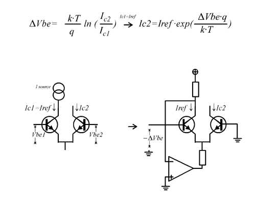
The main VCA is a
differential pair + current source. It uses a variation on an
exponential converter to multiply the volume CV with the main envelope and drive the main VCA.
Envelope Generator
This is a decay-only envelope generator. C20 is the core of it. It's charged by a trigger through T5 and drained by Q2.
Transistor pair Q2 and Op-Amp IC6B also look like a variation on an
exponential convertor. They serve as a current sink to voltage control the draining of C20(decay).
T6, C22 and R55 form a second, simpler envelope generator. It works the same way, minus voltage control.
VCF
There is only one VCF per voice. The entire mix is passed through this filter before hitting the main VCA.
It's a
standard Sallen-Key low-pass filter. The resistive elements are realised with more 4016 switches. IC15B biases it to a virtual ground sitting at +2.5V. This is so the signal falls within the 4016's supply rails.
4016 CV
As I've said, the 4016 switches need to be given a duty-cycle (PWM) signal to change their resistance. This is accomplished by generating a sawtooth wave (labeled PWM_4016) and comparing it to a CV signal.
For example, the filter CV (FLT_CV) is fed into buffer IC8C, passively mixed with the main envelope and biased toward the positive rail. This signal, along with our sawtooth are fed into comparator IC4B and output to the 4016.
When the CV signal is higher than the sawtooth, the output is high. When the CV is lower than the sawtooth, the output is low.
This page demonstrates it nicely with this image:
The result is a pulse-width modulated wave that reflects the incoming CV.
CV Mux
The control logic (not pictured) generates CV signals and
multiplexes them over one connection: MUX_CV. The CV's destination is defined by signals 4051_A, B and C.
The CV Mux circuit de-multiplexes the CV signals from the control logic. It select the output that corresponds to the 4051 signals and connects it to the incoming CV signal. This charges a capacitor at the output. Once the multiplexer moves on to the next output the previous output goes
hi-Z. This prevents the multiplexer from draining the capacitor and allows the capacitor to retain its voltage.
In this way, the multiplexer is also a multi-output
sample and hold, grabbing voltages and holding onto them.
Noise
The noise circuit is part of the control logic, so is not pictured with the rest. It's built around a reverse biased 2SC1815 NPN transistor, similar to the 808's. It's lowpass filtered before being sent to the separate voices.
Odds and Ends
There are some unconnected and strangely arranged components. I'm guessing these are utilised in the other voice configurations.
The most obvious one is IC13 (4016). It has two switches connect to the attack VCA's output and not much else. They look like the start of a
sallen key high-pass filter, but there's no op-amp connected to them.
Here is a block diagram of one voice:
The full schematic images and eagle files are on my github
here.


