I'm generally interested in analog drums, so I wanted to try understanding the design. Unfortunately, there doesn't seem to be a copy of the schematic anywhere. So, I took some photos of the board and pieced together a schematic. The five voices are nearly identical, so only redrew one. Here it is:

To give a general summary, each voice has 3 VCOs, 1 Lowpass VCF, 2 Envelope generators and 5 VCAs
If you compare schematics, it looks like it evolved out of the Syncussion. The strange transistor-pair and CMOS inverter clusters have been (mostly) replaced with more normal OTAs. Some portions of the schematics are still nearly identical. The envelope generator and final VCA for example.
Another part of the evolution is the presence of CMOS bilateral switches. When switched at a high frequency, they act as duty-cycle controlled resistors. If switched by a VCO with voltage controlled duty-cycle, they act as voltage controlled resistors.
There are two 4016s per voice, used to voltage control the various VCO pitches and filter cut. Strangely, they are run on a +5V rail, while the rest of the system runs on ±8V.
VCOs
There are three identical, but differently tuned VCOs. One is the regular, fundamental tone of the drum. Two serve to generate the "overtone" signal, a somewhat atonal sound that can be mixed with the fundamental.The VCOs are a pretty standard 4069 square/triangle oscillator design. In this case, only the triangle output is used. Most designs include a potentiometer for pitch adjustment. These instead use a 4016 switch to implement voltage control. They cannot be tuned separately due to sharing the same CV signal.


VCAs
All but the main VCA use the same LM13700 design. It's the bare minimum, leaving out the buffer and bias diodes. Here it is compared to the example from the datasheet:

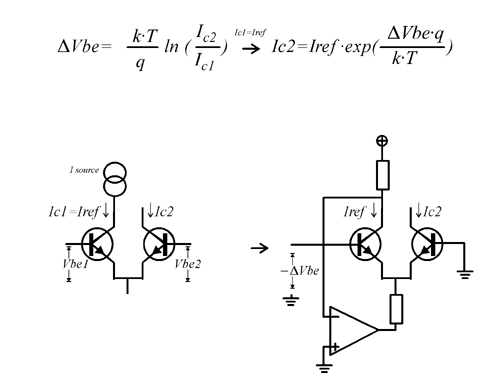
The transistor pairs driving them are more interesting. I've only ever seen them in hand clap circuits. They form a differential pair, but are biased to be an exponential current source.

The transistor pairs driving the "Attack VCA" and "Over-T VCA" (pairs T1 and T4) are also acting as VCAs themselves. They're multiplying the CV at the base with the Envelope CV coming in the emitter. This allows voltage control over the volume without changing the envelope.
The pairs driving the "VCO/Noise Bal" are opposites of each other. That is to say, one pair is inverting and the other is non-inverting. This lets one CV signal mix the VCO and Noise signals relative to each other.
Over Tone VCA
This VCAs serves to mix out the over tone signal based on the main envelope. This gives more over tone signal at the start of the sound and less at the tail.Attack VCA
This VCA lets in a quick burst of noise to simulate a real drum transient.Main VCA
The main VCA is a differential pair + current source. It uses a variation on an exponential converter to multiply the volume CV with the main envelope and drive the main VCA.
Envelope Generator
This is a decay-only envelope generator. C20 is the core of it. It's charged by a trigger through T5 and drained by Q2.Transistor pair Q2 and Op-Amp IC6B also look like a variation on an exponential convertor. They serve as a current sink to voltage control the draining of C20(decay).
T6, C22 and R55 form a second, simpler envelope generator. It works the same way, minus voltage control.
VCF
There is only one VCF per voice. The entire mix is passed through this filter before hitting the main VCA.It's a standard Sallen-Key low-pass filter. The resistive elements are realised with more 4016 switches. IC15B biases it to a virtual ground sitting at +2.5V. This is so the signal falls within the 4016's supply rails.


4016 CV
As I've said, the 4016 switches need to be given a duty-cycle (PWM) signal to change their resistance. This is accomplished by generating a sawtooth wave (labeled PWM_4016) and comparing it to a CV signal.For example, the filter CV (FLT_CV) is fed into buffer IC8C, passively mixed with the main envelope and biased toward the positive rail. This signal, along with our sawtooth are fed into comparator IC4B and output to the 4016.
When the CV signal is higher than the sawtooth, the output is high. When the CV is lower than the sawtooth, the output is low. This page demonstrates it nicely with this image:

CV Mux
The control logic (not pictured) generates CV signals and multiplexes them over one connection: MUX_CV. The CV's destination is defined by signals 4051_A, B and C.The CV Mux circuit de-multiplexes the CV signals from the control logic. It select the output that corresponds to the 4051 signals and connects it to the incoming CV signal. This charges a capacitor at the output. Once the multiplexer moves on to the next output the previous output goes hi-Z. This prevents the multiplexer from draining the capacitor and allows the capacitor to retain its voltage.
In this way, the multiplexer is also a multi-output sample and hold, grabbing voltages and holding onto them.

Noise
The noise circuit is part of the control logic, so is not pictured with the rest. It's built around a reverse biased 2SC1815 NPN transistor, similar to the 808's. It's lowpass filtered before being sent to the separate voices.

Odds and Ends
There are some unconnected and strangely arranged components. I'm guessing these are utilised in the other voice configurations.The most obvious one is IC13 (4016). It has two switches connect to the attack VCA's output and not much else. They look like the start of a sallen key high-pass filter, but there's no op-amp connected to them.


Here is a block diagram of one voice:

The full schematic images and eagle files are on my github here.
Hi.
ReplyDeleteNice work!. could I have a bigger picture of the main schematic? I'm in the process of fixing a machine where there is almost no noise. I suspect the 4558 opamp, but it could well be the mixer part. BTW. the schematics for the 5 channels are not identical. just above the 4016 ic there a re differences in capacitors. the snare has a film capacitor, the base a 222 cap, and th all the three toms have a 102k cap. also there are different caps just above and left of the second row of 4069 chips have different values.
thanks for the great work!
Simon
Hi Simon,
ReplyDeleteThank you! I've uploaded a larger schematic to my github. The link is at the end of the post.
You're correct; the voices differ slightly. That's why I said "nearly identical".
Also, I didn't make note of component values. If you'd like to add some to the schematic it would be appreciated.
Let me know how the noise fix goes. I'd bet on the 4558 too.
Best of luck,
Zack
thanks for the schematic. i found a defective 1uf elco near the noise transistor so after swapping that one out noise was back!
Deletein the mean time i've made a midi adapter to trigger, change programs and alter settings via cc messages. was quite a thing to do but it works quite nicely, although i had to use two arduino's to do that due to timing constrains. i'm planning on doing a writeup but am very busy right now at work and working on converting a moog satellite from a thomas organ to something with more knobs and posibilities
Simon,
DeleteYou're welcome. That's fine detective work!
I've also made a MIDI retrofit for velocity triggers and all 40 parameter changes. I'll do a write up as well.
I look forward to seeing yours. It'll be fun to see two solutions to the same problem. Does your approach use the external connectors?
That Moog Satellite sounds very interesting too.
Godspeed,
Zack
my first midi retrofit was external and only used the trigger and program changes ports on the back, but i gave that one away after finishing the internal one. I've opted to inject data into the sram chip so all the digital to analog stuff is handeled by the drum-x itself and you can see the changes on the display on the front. I even build a 40knob midicontroller to act as a man in the middle and can inject 40 cc values into a existing midi stream: http://photo.simski.org/picture.php?/162/category/11
DeleteOh, that's really cool. I'd like to see exactly where in the timing cycle you're controlling the SRAM. That's probably tricky, huh?
DeleteI bypassed all the digital, sync'd with the main counter chip and injected my own 8-bit CV. I like the added bit-depth, but I do wish that the main display/controls could tie in somehow. There is a toggle to revert back to them though.
I like the knobby controller too. Is that another arduino and some muxes? I just use a BCR2000 or Beatstep Pro.
yes, it is tricky, hence the two arduinos used for everything. timing is very critical and i had to do a lot of direct port manipulation to get it right. but it works flawlessly now, although the eight memory positions are always in a flux now.
Deletei'm planning to do a small batch of the pcb's as soon as i have finished the layout.
Now I'm wondering how you synchronized two arduinos. I'm intrigued.
DeleteI imagine you've got a pretty good understanding of the digital side of it now. Would you mind adding notations/cleaning-up the digital control schematic?
I made a few functional, but flawed, PCBs. A new batch is on the way.
How do you plan on mounting yours?
the thing with syncing the two arduinos is: I don't. they are hooked up to the same serial in and one manages the triggers and program changes, the other manages the cc values and data injection. I've mounted my board on two hexagonal risers on the original screwmounts in the right back corner above the sawtooth/noise generator. I am unable to locate pictures of my setup atm. I also placed the 7808 on the side of the chassis close to the mounting hole for the lid so it gets more cooling. on that spot, the screw for the 7808 sits behind the lid and is invisible. I mage a mistake though as it was a little too close to the mounting hola as the dimple in the side of the lid was bigger than anticipated.
Deleteas for the schematic, I am unabl to open it as i don't have Eagle anymore. I'm on Kicad now as my pc's run Ubuntu linux. could you export your schematics to pdf so i can take a look at them?
DeleteSorry I took so long, but I've added a PNG of the control circuit to my github.
Deleteah. thanks. will look at it to see if i've missed something.
DeleteThanks. i've downloaded the digital schematic and will look into it. probably i just print it and add my notes to it
DeleteHi,
ReplyDeleteHave you seen the mods that this did to his unit? https://www.stereoping.com/pearl-drx-1-drumsynth/?lang=en
I was hoping to have mine modified in a similar manner, but with jack plugs for CV modulation signals from Bitwig.
Do you think it may be possible to control this machine with CV signals?
Thanks,
Chris
Hi Chris,
DeleteYes, I've seen those mods. They're part of what inspired me to explore the machine!
It is absolutely possible to control it with external CV. One way would be to sever the existing CV connections near the multiplexer(s) and route them through switched jacks. That way it will accept CV when cables are plugged in, but still work normally without them.
Be mindful of the voltages though. The internal CV comes from digital logic and only spans 0-5V. You'll want to keep your CV in a similar range. I recommend protection diodes, voltage dividers and maybe buffers on the inputs.
Depending on what you're wanting, it might be better/easier to build it to accept MIDI. You can have something like an arduino doing the MIDI to CV and manipulating the muxes. I can upload my schematic of the digital control side to help with this.
Let me know,
Zack
Thanks for the reply Zack,
ReplyDeleteThe schematic for the digital control side, would be a handy addition to forward to my tech guy.
I guess the parameters are not as time sensitive as the triggers, so the Midi to CV solution sounds logical and would require far less drilling, wiring etc.
Am I looking for something that can do 8 channels of CV?
This configurable Kenton unit does 16 channels, but in the opposite direction: http://www.kentonuk.com/products/items/projects/an16.shtml
Cheers,
Chris
Chris,
DeleteI've added the control schematic to my github. I never fully reverse engineered it, but I labeled what I could.
For the CV converter, I would take advantage of the way it's already set up. The control board actually only generates one CV signal at a time. It just multiplexes it to the 40 destinations(8 parameters * 5 voices). It controls the muxes and CV with some convoluted CMOS logic, but it can be done more simply.
Personally, I wouldn't try to do it with off-the-shelf MIDI to CV converters, because they can't control the muxes. I'd use a microcontroller + DAC and write something custom. I'm kind of tempted to try it now.
- Zack
Guys, can any of you build an external box to sequence this via MIDI and control these parameters via knobs and CV inputs?
DeleteI will pay for it. Thinking to add like a D-sub connector at the rear of the DR-X and that way keep the rack unit neat on the outside.
Sure. I already have PBCs for my internal MIDI retrofit. There's a general overview:
Deletehttp://zeninstruments.blogspot.com/2018/03/pearl-drum-x-midi-control.html
Thanks Zac,
ReplyDeleteRegarding the hack to achieve a wider range on the controls, would that still need to be done going the midi to CV route?
Some of the stuff I did find:
https://github.com/FortySevenEffects/arduino_midi_library
https://midisizer.com/midi2cv-mk2/
http://orchardelica.com/wp/?page_id=558
https://www.pjrc.com/teensy/td_libs_MIDI.html
- Chris
Chris,
DeleteYes, the range mods are separate from everything else. Although, the CV you end up generating may also impact the pitch/decay ranges.
Those all look like like good projects to build on. I'm seeing a lot of serial DACs though. Those might be fine, but a simple parallel DAC would make things easier. You'll need to quickly change your CV and keep it in sync with the muxes. A serial DAC introduces a (very small) delay that will slow things down and skew the timing.
Keep me posted on any progress.
- Zack
I've reached out to Sebastian Tomczak who has some nice midi/cv projects on his site, including this one which could be ideal for the analogue approach of Stereoping : https://little-scale.blogspot.com.au/2017/11/usb-midi-to-eight-gates-and-sixteen-cv.html
ReplyDeletelittle-scale does some very cool stuff, and that's a nice project, but 16 CV outputs will only cover 2 voices if not multiplexed. It's overkill to have more than one DAC output, unless you really want to avoid the muxes for some reason. Just to be clear, both approaches are equally "analog" as the muxes are analog.
DeleteRegardless, for multi-outs I wouldn't use the 2-output DACs he uses. We don't need 12-bit precision and MIDI only (typically) sends 7-bit anyway. I'd instead jump up to some 8-output ones. I've had success using the MAX528 for example. You can chain 5 of them together to controll all 5 vices.
If you don't mind including me in the conversation, I'd like to see what Mr.Tomczak says. I can send you an email so you'll have my address.
-Zack
Yes I pointed Tom to this post, so he may chime in here....if not I'll let you know of any replies I receive. Turns out Tom is associated with the university of Adelaide, maybe a kilometer from where I live....so he could certainly check out my Drum-X if he became interested.
ReplyDelete-Chris
Well, that's pretty cool!
DeleteI've spread myself thin at the moment, but I'll try to crack open the DRUM-X again.
Hi,
ReplyDeleteReally interesting reading this article. I'm into my synths and managed to picked one of these up. I wanted to get the some mods done, however, when I switched it on it worked for about 5 mins then a hum got louder and then it popped. When I turn it on now the display flashes briefly and then all goes dead.
I have a little experience in this field and think it's probably power supply related but wondered if you had any ideas..
I would love to get this machine working and wondered if you had an ideas on the cause or where I should start.
Really grateful for anything.
Best regards,
Chris
Hi Chris,
ReplyDeleteThis is almost certainly a power supply issue. Transformers are typical sources of hum and capacitors tend to pop.
I would remove and test anything that looks (or smells!) suspect in the power section.
If you can take some pictures, I might be able to identify something.
- Zack
Hi Zack,
ReplyDeleteThanks for taking the time to respond.
I've looked at the power supply and the only thing I can see is the 7805 voltage regulator looking corroded and split at the top. I can't see where I could add an image to this message as that would explain better.
Everything else looks fairly clean and original, so I don't know if I'd be better to replace the regulators and caps in one go as I assume they are original and would probably need replacing anyway?
Again, grateful for any advice.
All the best,
Chris
Chris,
DeleteYou can send pictures to my email, zacknelson1@gmail.com.
There's not much on that power supply board. It wouldn't hurt to just replace every component.
If you want to diagnose it a little, you could disconnect it from the main PCB and test each rail. You can also try running the main board off of a bench supply.
Let me know what you find.
- Zack
Hi Zack,
DeleteThank you.
I just sent some pictures to your email address. If you spot anything or need pictures of anything else then please let me know.
I suspect I'll need to replace everything. Like I said, it's just been a while.
Cheers,
Chris
This comment has been removed by a blog administrator.
ReplyDelete